 English
  ελληνικά
  Esperanto
  Afrikaans
  tiếng Việt
  Català
  Italiano
  שפה עברית
  Cymraeg
  العربية
  Gaeilge
  český
český  Eesti Keel
  Galego
  Indonesia
  Español
  русский
  Nederlands
  Português
  Norsk
Norsk  Türkçe
  Lietuvos
  Latviešu
  Pilipino
  ภาษาไทย
  Română
  icelandic
  Polski
  ייִדיש
  беларускі
  Français
  български
  український
  Hrvatski
  Deutsch
  Kreyòl ayisyen
  Dansk
Dansk  فارسی
فارسی  हिन्दी
  Suomi
Suomi  magyar
  日本語
日本語  Srpski језик
  Shqiptar
  한국어
한국어  Svenska
  Македонски
  Slovenský jazyk
  Malti
Malti  Malay
Malay  Slovenski
  lugha ya Kiswahili
  አማርኛ
አማርኛ  Azərbaycan
  Euskal
  Bosanski
  Frysk
Frysk  ភាសាខ្មែរ
  ქართული
  ગુજરાતી
  Қазақша
  Hausa
Hausa  Кыргыз тили
  ಕನ್ನಡ
ಕನ್ನಡ  Corsa
Corsa  Kurdî
Kurdî  Latine
  ລາວ
ລາວ  Lëtzebuergesch
  Malagasy
  मराठी
मराठी  മലയാളം
  Maori
Maori  Монгол хэл
  বাংলা ভাষার
  Burmese
  Hmong
Hmong  IsiXhosa
  नेपाली
  Punjabi
  پښتو
پښتو  Chichewa
  Samoa
Samoa  Sesotho
  සිංහල
සිංහල  Gàidhlig
  Cebuano
  Somali
  Тоҷикӣ
  తెలుగు
  தமிழ்
தமிழ்  تمل
تمل  O'zbek
  Hawaiian
  سنڌي
سنڌي  Shinra
  Հայերեն
  Igbo
Igbo  Sundanese
  Javanese
  Yoruba


 Co.,Ltd")


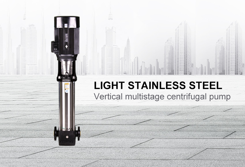
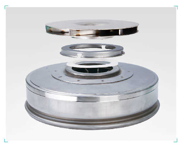
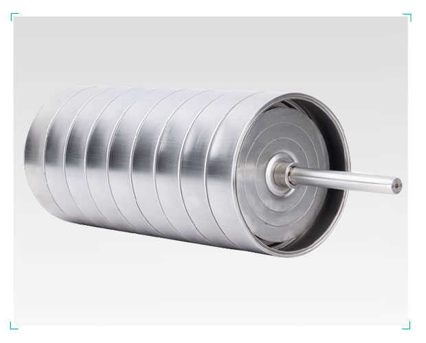
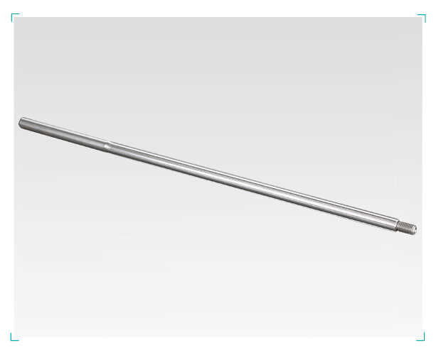
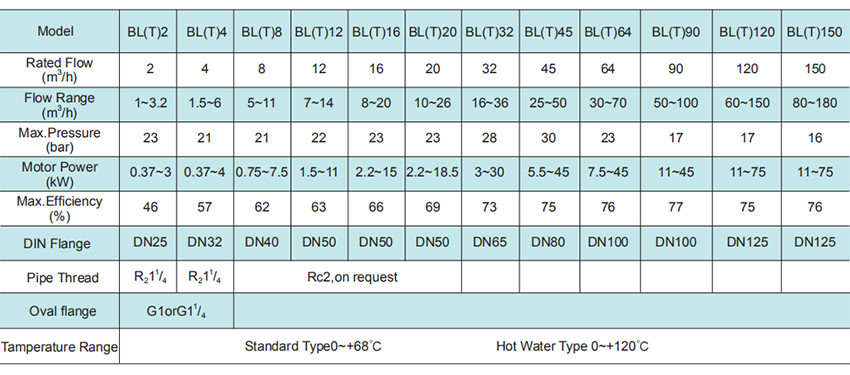
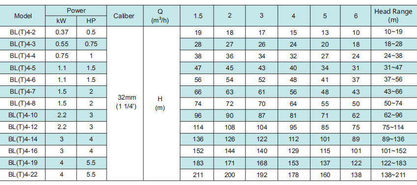
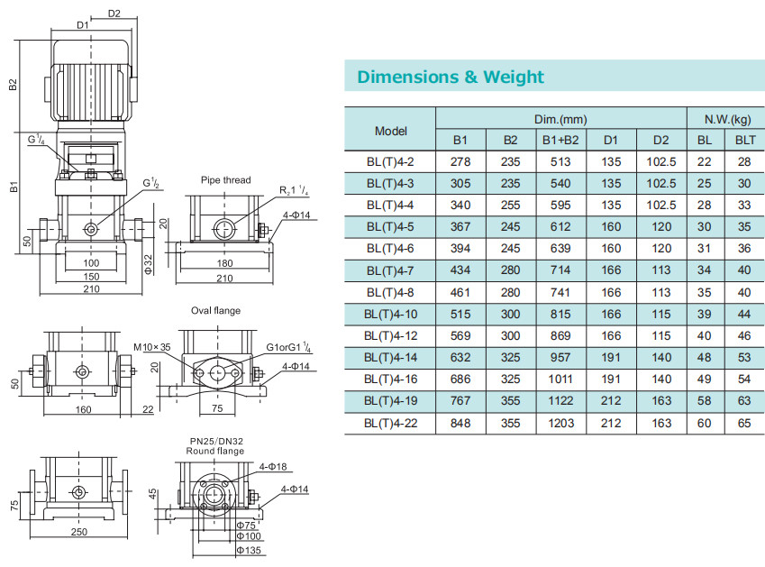
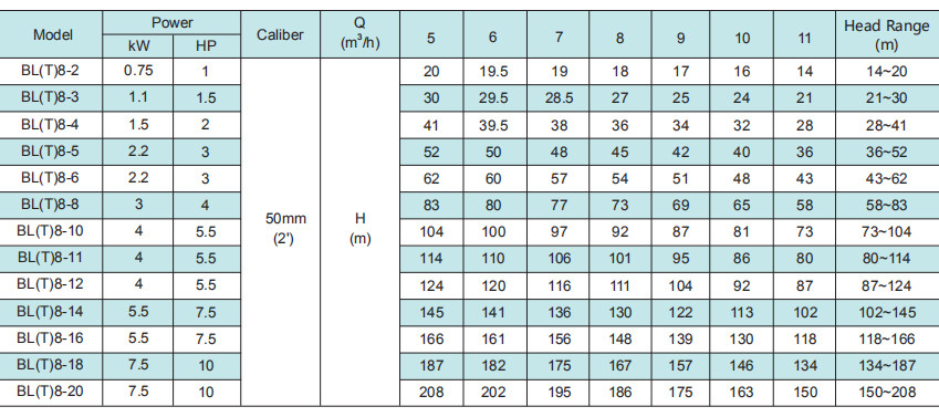
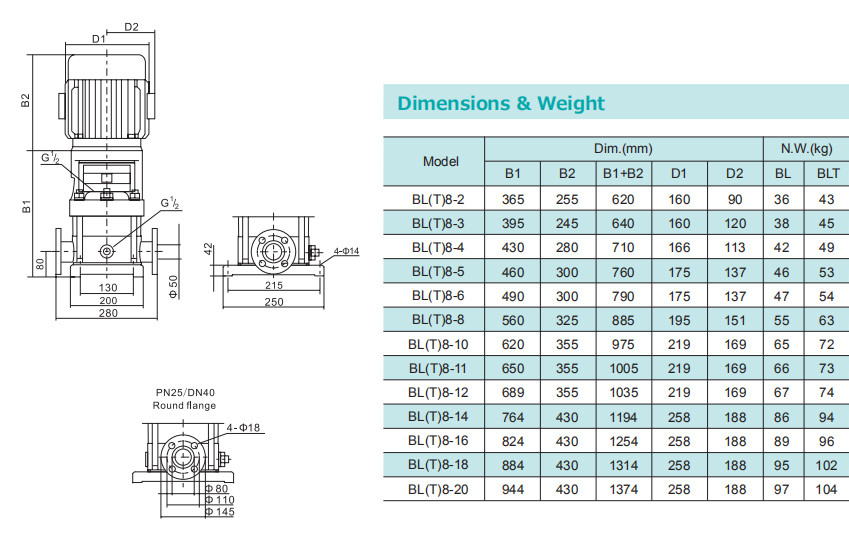
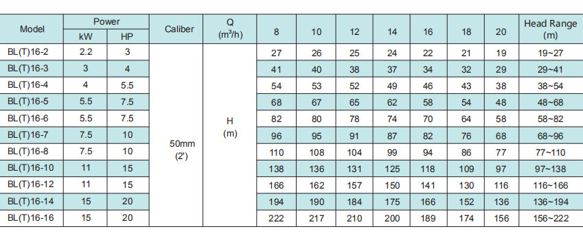
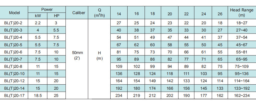
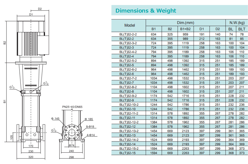
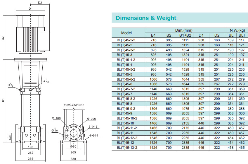
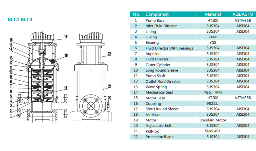
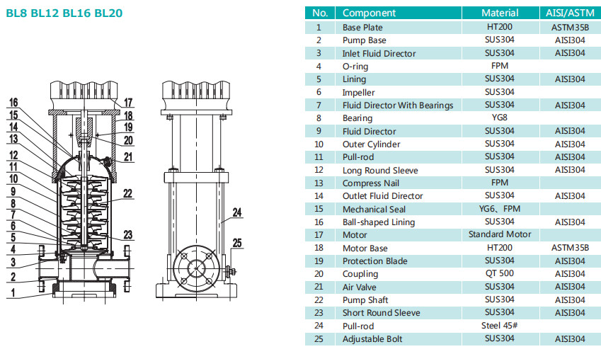
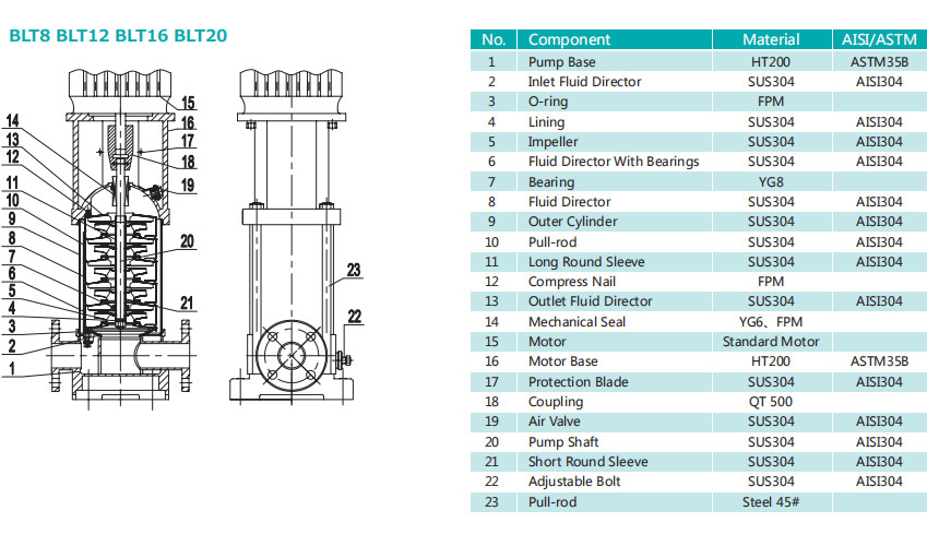
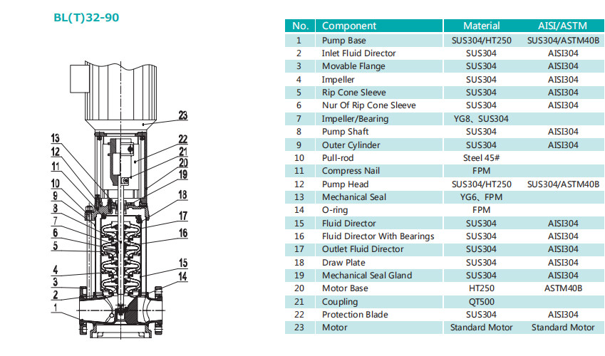
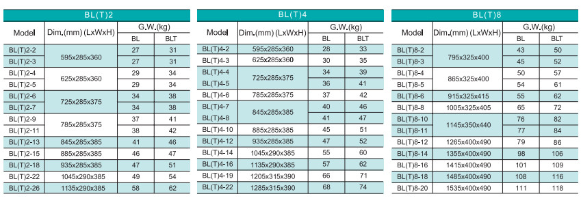
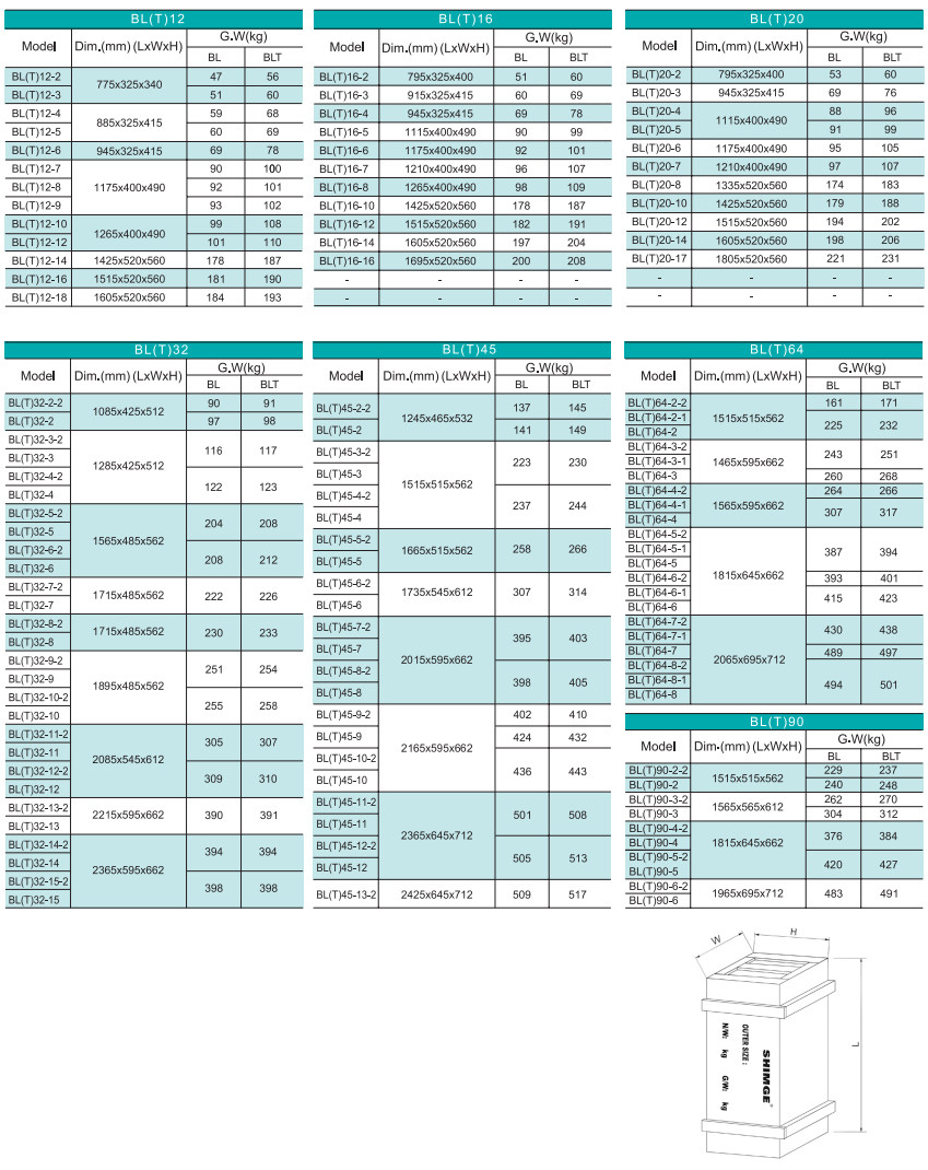
BL(T) series stainless steel multi-stage centrifugal pump (afterwards called pump)boasts characters of high efficiency, low noise, steady operation, etc.The pump set adopts the non-self-priming vertical multi-stage structure, which makes a compact whole,its installation easy, its operation and maintenance convenient.
|
Water supply |
BL |
BLT |
|
Filtration and transfer at waterworks |
● |
● |
|
Distribution from waterworks |
● |
● |
|
Pressureboosting in mains |
● |
● |
|
Pressure boosting in high-rise buildins,hotels,etc. |
● |
● |
|
Pressure boosting for industrial water supply |
● |
● |
|
Industry |
|
|
|
Pressure boosting |
|
|
|
Process water systems |
● |
● |
|
Washing and cleaning systems |
● |
● |
|
Vehicle washing tunnels |
● |
● |
|
Fire fighting systems |
● |
● |
|
Liquid transfer |
|
|
|
Cooling and air-conditioning systems(refrigerants) |
● |
● |
|
Boiler feed and condensate systems |
● |
● |
|
Machine tools(cooling lubricants) |
● |
● |
|
Aquafarming |
● |
● |
|
Transfer |
|
|
|
Oil and alcohol |
● |
● |
|
Glycol and coolants |
● |
● |
|
Water treatment |
|
|
|
Ultra-filtration systems |
● |
○ |
|
Reverse osmosis systems |
● |
○ |
|
Softening, ionising, demineralizing systems |
● |
○ |
|
Distillation sys tems |
● |
○ |
|
Separators |
● |
○ |
|
Swimming baths |
● |
● |
|
lrrigation |
|
|
|
Field irrigation(flooding) |
● |
● |
|
Sprinkler irrigation |
● |
● |
|
Drip-feed irrigation |
● |
● |

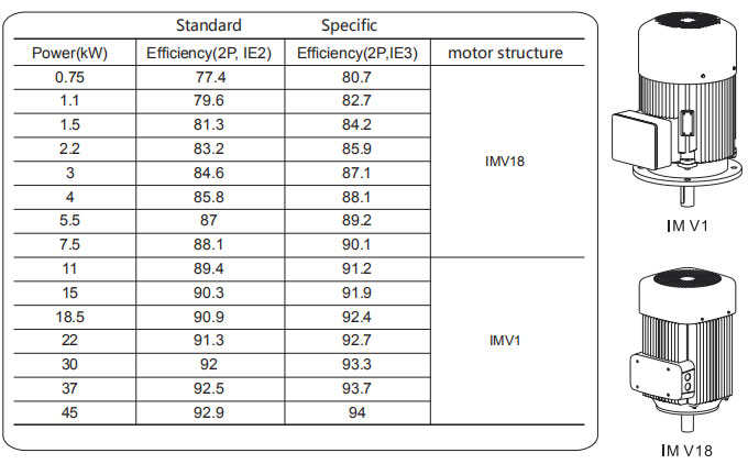
Energy Efficiency Standard (IEC60034)
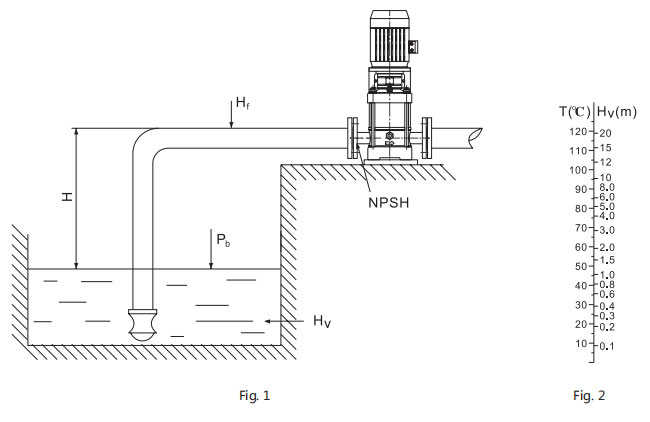
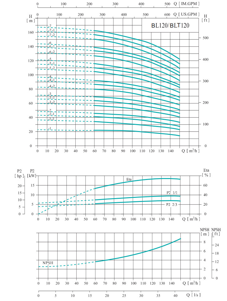
Calculation Of minimum Inlet Pressure
If the pressure in pump is lower than the vapour pressure of medium, cavitation will occur, which will affect the performance of pump. To avoid the cavitation and ensure the pump inlet has a minimum pressure, maximum suction head should be calculated as following:
H=Pbx10.2-NPSH-Hf-hv-Hs
Pb: Atmospheric pressure, bar (In close pipeline system, it can be considered as the system pressure );
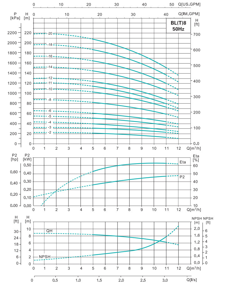
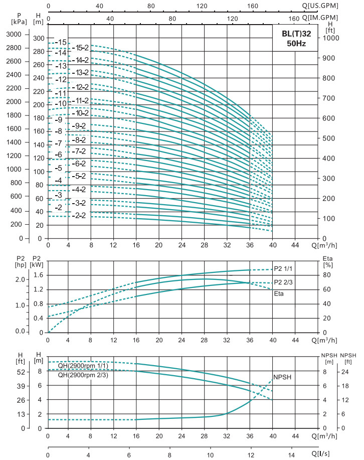
NPSH: Net positive suction head, m (Value at maximum flow of Q-NPSH curve);
Hf: Suction pipe line loss (Value at maximum flow of corresponding pipeline);
Hv: Medium vapour pressure, m (Medium vapour pressure at corresponding temperature, the default medium is water, as shown in figure4 on the right );
Hs: Safety margin, m, general value is 0.5.
Calculation result: if H is positive, the pump is installed in suction way, otherwise, it is installed in downdraft way.
Note: It is not necessary to do above calculation under general conditions. Only when we use pump in the following situations do we need to calculate the H:
1. Medium temperature is high;
2.The velocity of flow is larger than rated value;
3.Suction head is big or inlet pipeline is long;
4.System pressure is small;
5.Inlet condition is bad.
Selection Of Pumps
Selection of pumps should be based on:
Duty point of the pump.
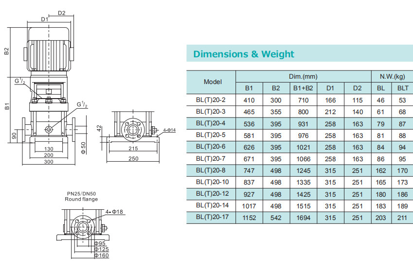
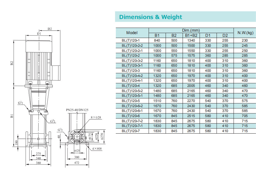
Dimensional data such as pressure loss as aresult of height differences,friction loss in the pipework,
Pump efficiency etc.
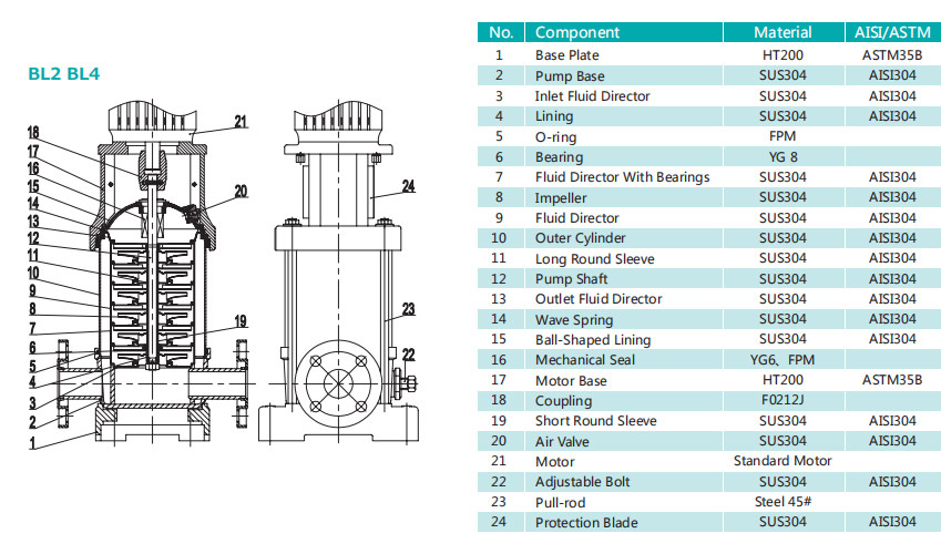
Pump materials
Pump connections
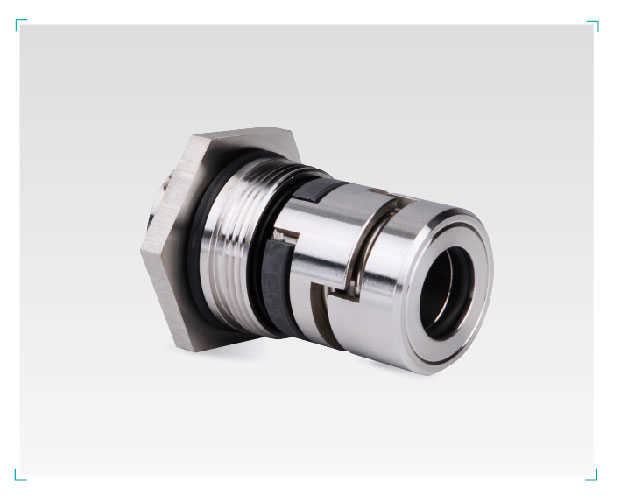
Commonly used mechanical seal configuration tables
1. Duty point of the pump:
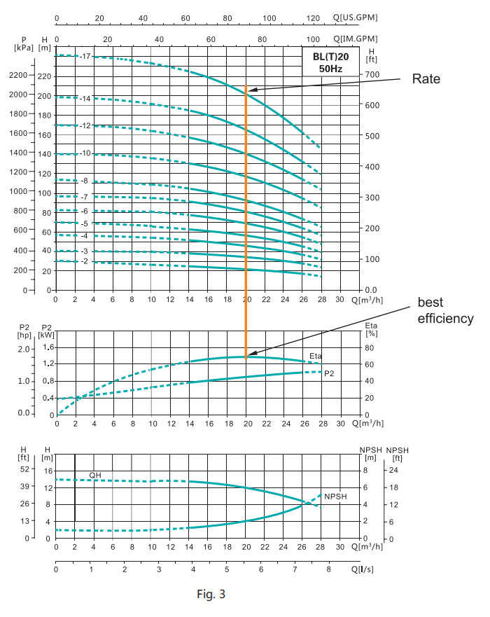
From a duty point it is possible to select a pump on the basis of the curve charts shown in "performance curves/technical" data.2. Dimensional data:
When sizing a pump the following must be taken into accounting: •Required flow and pressure at the draw-off point. •Pressure loss as a result of height differences. •Friction loss in the pipework(Hf) (Refer to Fig.1) It may. •Best efficiency at the estimated duty point. •NPSH value. •For calculation of the NPSH value, see corresponding curves chart.3. Pump efficiency:
Before determining the best efficiency point, the operation pattern of the pump needs to be identified. If the pump expected to operate as the same duty point, then select a BL pump which is operating at a duty point corresponding with the best efficiency of the pump.As the pump is sized on the basis of the highest possible flow, it is important always to have the duty point to the right on the efficiency curve(eta) in order to keep efficiency high when the flow drops.
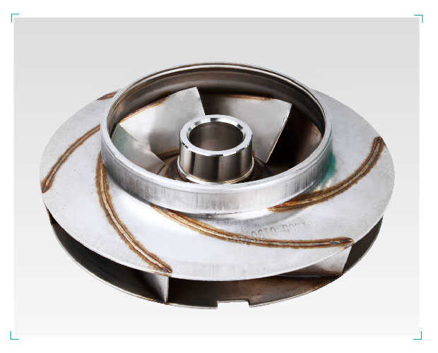
4. Pump material:
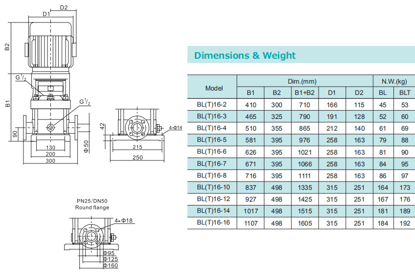
Selection of pump connection depend on the rated pressure and pipe work. the pump offer a wide range of ftexible connection such as:
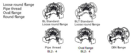
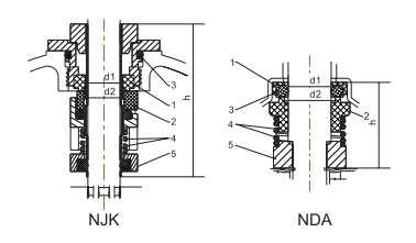
5. Commonly used mechanical seal configuration tables
| Application Field | Shaft seal type | Shaft seal material | ||||||||||
| Normal | Special | 1 | 2 | 3 |
4
5
|
Type key | ||||||
| Rotating part | Code | Stationary part | Code | Elastomers | Code | Compression spring | Collor | Code | ||||
| 0℃ to +90℃ clean water | ● | Graphite | A | SiC | S | FPM | F | SUS304 | C | ASFC | ||
| 0℃ to +90℃ clean water | ● | WC | W | Graphite | A | FPM | F | SUS304 | C | WAFC | ||
| +90℃ to +120℃ corrosion resistance | ● | SiC | S | SiC | S | EPDM | E | SUS304 | C | SSEC | ||
| up to 0℃ | ● | WC | W | WC | W | EPDM | E | SUS304 | C | WWEC | ||
| Mechanical seal type | Pump model | d1 | d2 | h |
| NJK | BL(T)2/4 | 12 | 12 | 55 |
| BL(T)8/12/16/20 | 16 | 16 | 57.5 | |
| BL(T)32/45/60/90 | 22 | 22 | 72 | |
| NDA | BW(J)2/4 | 12.7 | 16 | 32 |
| BW(J)8/16 | 17.4 | 20 | 33.5 |
|
Model |
Curve No. |
|
BL(T)2,4 |
2 |
|
BL(T)8,12,16,20 |
3 |
|
BL(T)32-2-2~BL(T)32-7 |
1 |
|
BL(T)32-8-2~BL(T)32-12 |
4 |
|
BL(T)32-13~BL(T)32-15-2 |
5 |
|
BL(T)45-2-2~BL(T)45-6 |
1 |
|
BL(T)45-7-2~BL(T)45-9 |
4 |
|
BL(T)45-10-2~BL(T)45-13-2 |
5 |
|
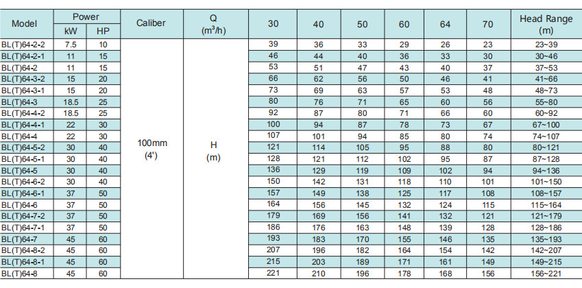
BL(T)64-2-2~BL(T)64-5-2 |
1 |
|
BL(T)64-5-1~BL(T)64-8 |
4 |
|
BL(T)90-2-2~BL(T)90-4-2 |
1 |
|
BL(T)90-4~BL(T)90-6 |
4 |
|
BL(T)120,150 |
6 |
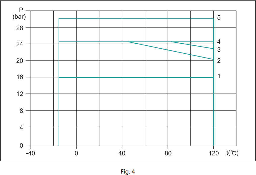
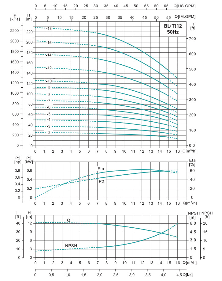
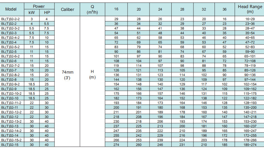
The limits of pressure and temperature are shown in the following fig.4,the pressure and temperature must be in the shown in the fig. 4.
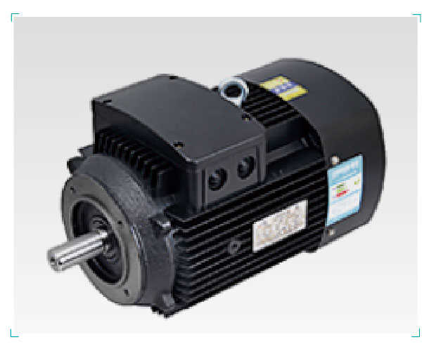
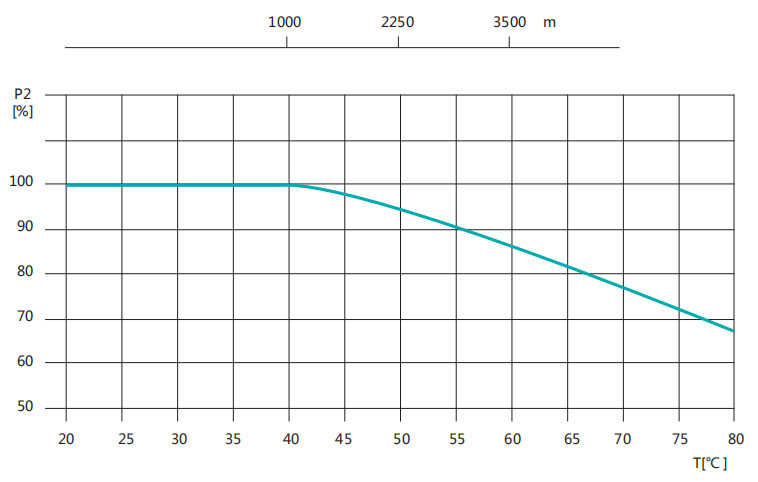
When the pump is operating in the place where ambient temperature is higher than 40℃ or altitude is higher than 1000m,the output power of motor P2 will decrease because of poor cooling caused by low air density.Therefore, in that case,the pump should be equipped with high-power motor.
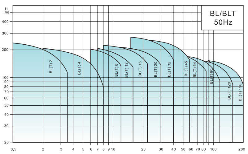
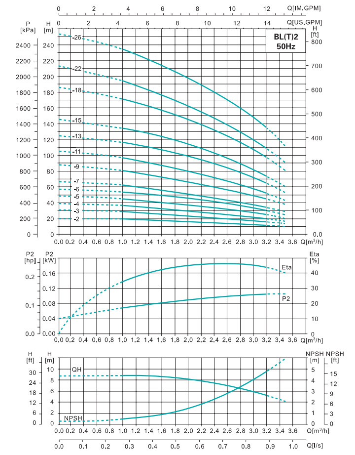
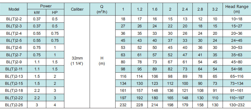
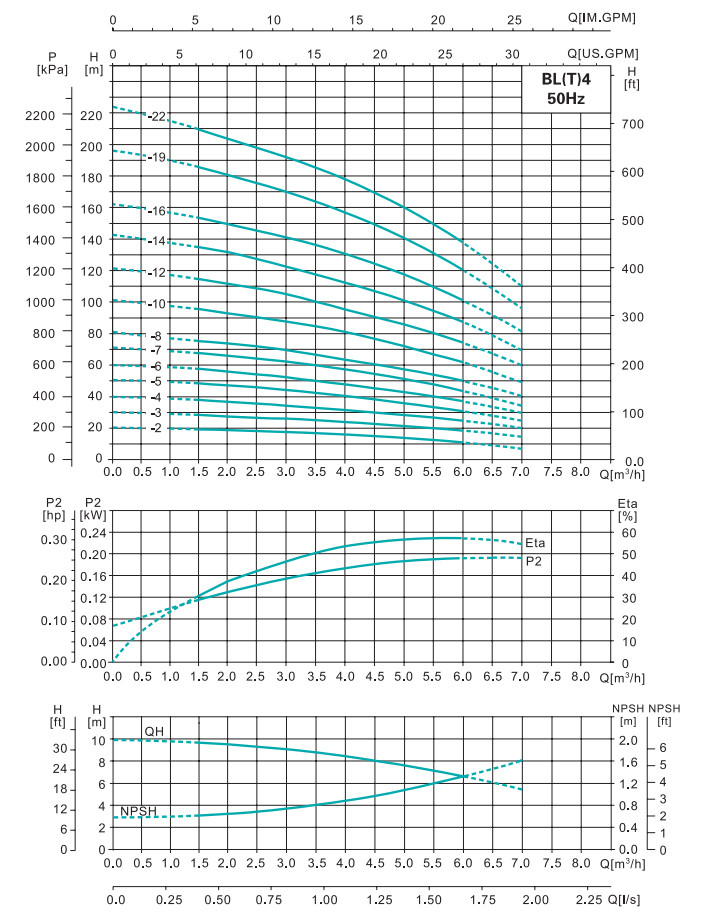
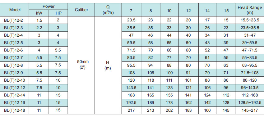
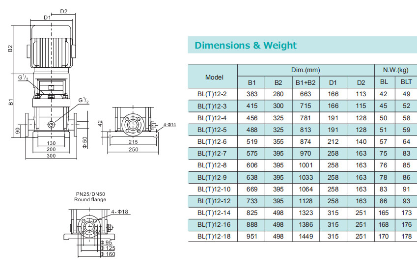
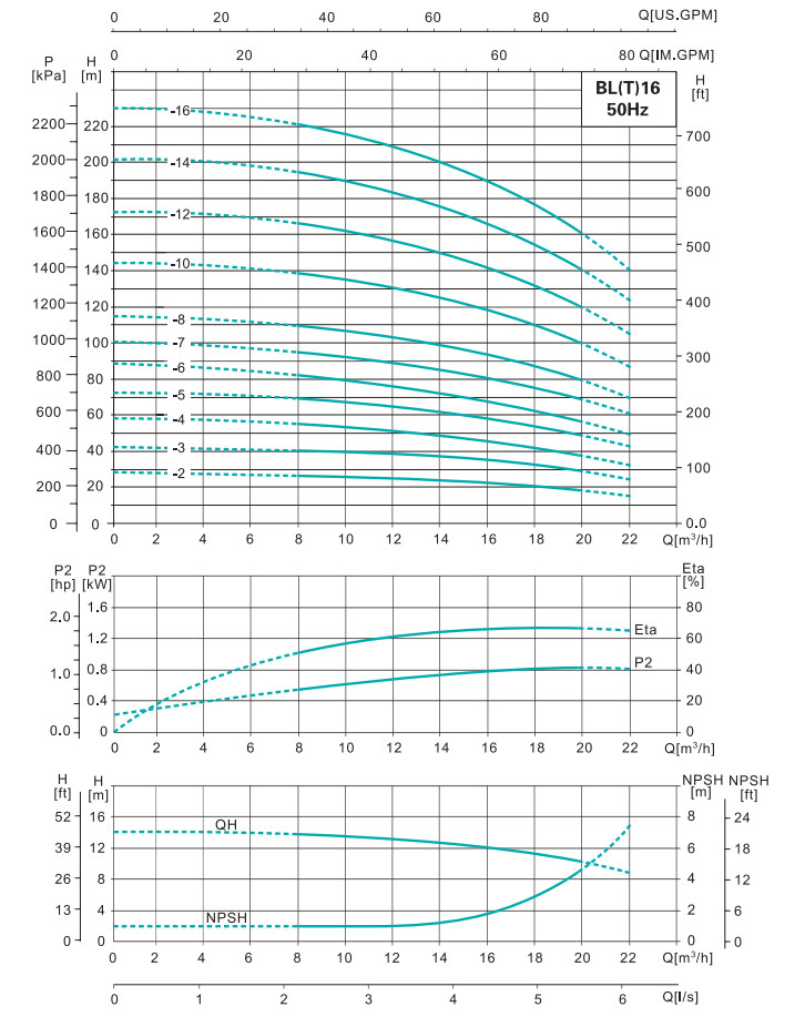
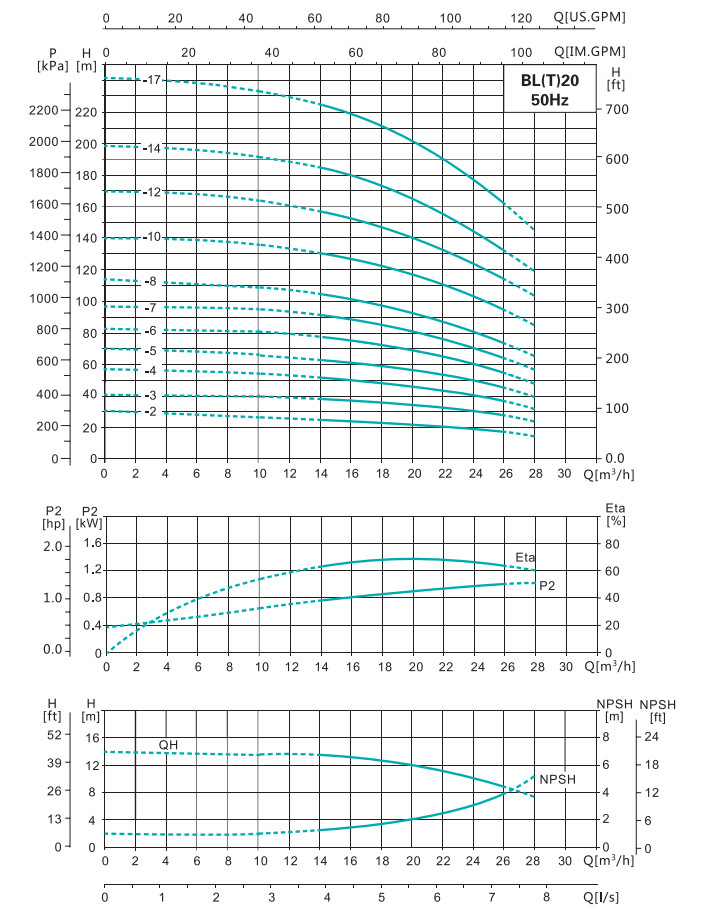
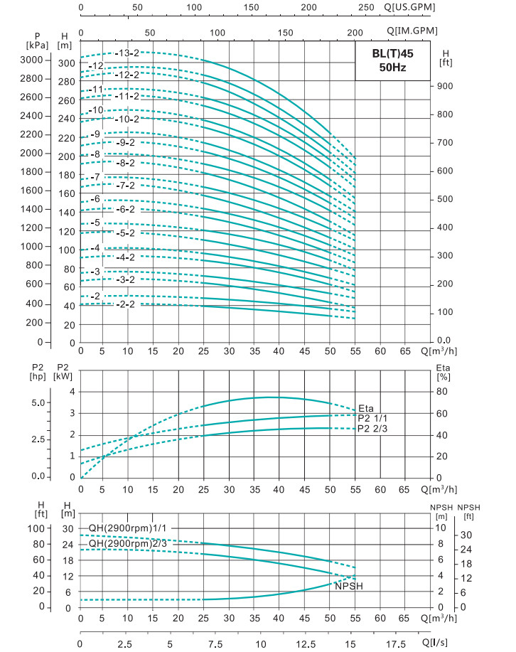
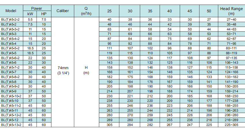
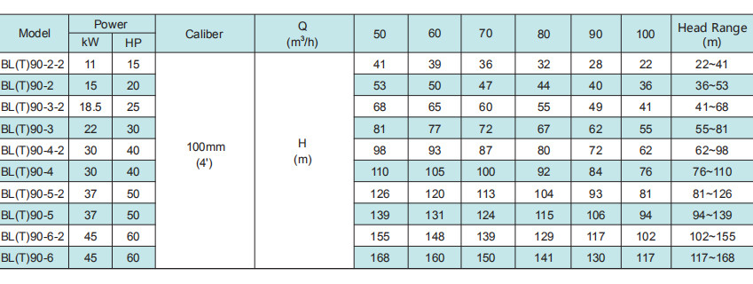
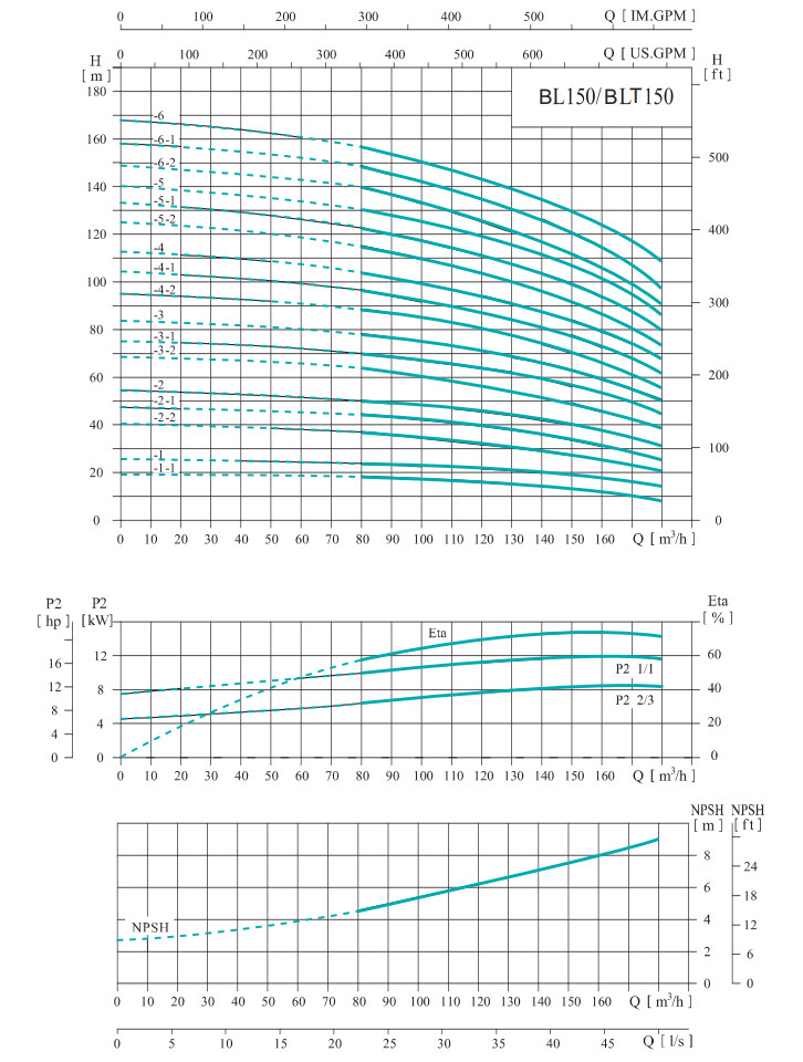
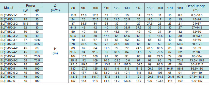
It is recommended to be used within lift range.
It is recommended to be used within lift range.
It is recommended to be used within lift range.
It is recommended to be used within lift range.
It is recommended to be used within lift range.
It is recommended to be used within lift range.
It is recommended to be used within lift range.
It is recommended to be used within lift range.
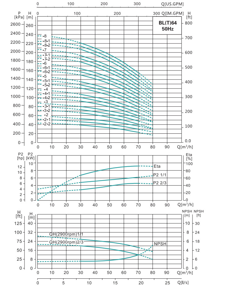
It is recommended to be used within lift range.
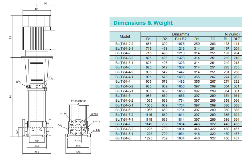
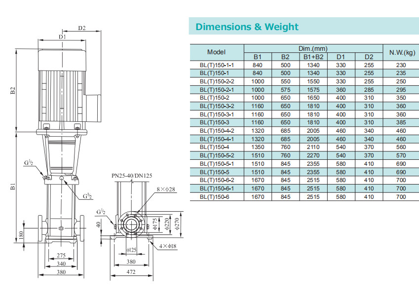
PN25-40/DN100 standard flange, on request.
It is recommended to be used within lift range.

PN25-40/DN100 standard flange, on request.
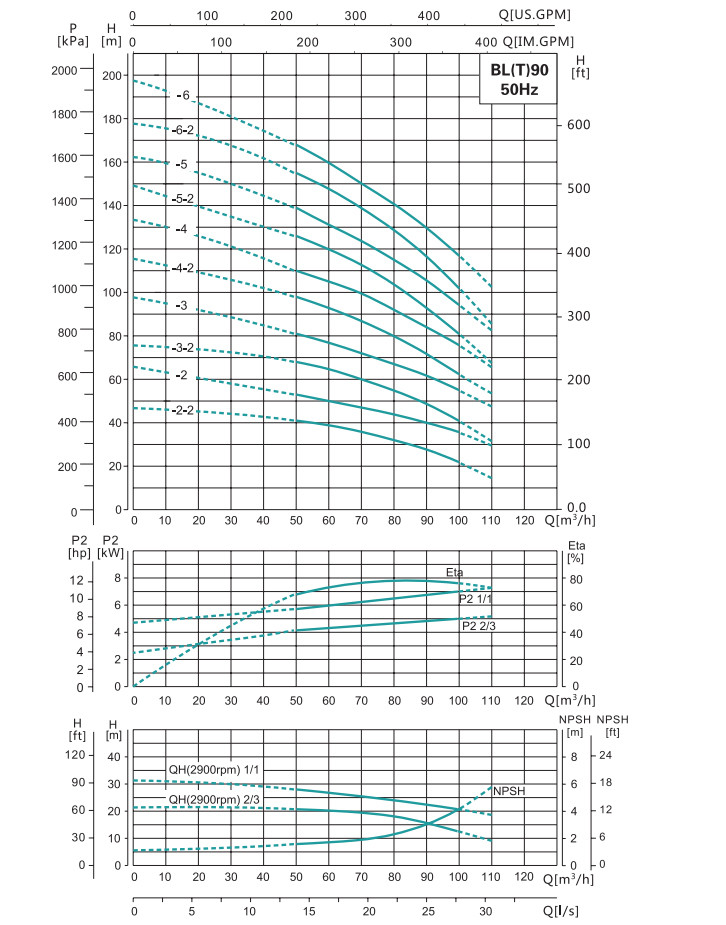
It is recommended to be used within lift range.
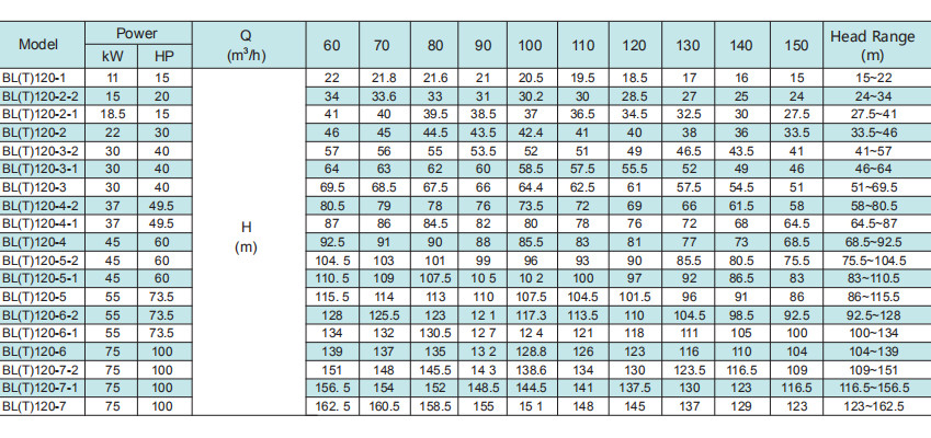
It is recommended to be used within lift range.

")


